Antennas and receivers for forward scatter set-ups
The antenna
Generally, Yagi antennas are used for meteor observations. An example is shown below for a 70 MHz Yagi (Figure 1). The dimensions depend on the resonant frequency of the aerial.
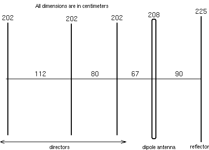 Figure 1 – The structure of a Yagi antenna for 70 MHz.
The reason why these antennas are popular is because they are easy to build and have a relatively high gain, i.e., they are sensitive in a given direction and less in others. The radiation pattern is typically like shown in Figure 2.
 Figure 2 – A typical horizontal radiation pattern of a horizontally polarized Yagi antenna.
The radiation pattern in the vertical direction is seriously altered by the presence of the ground. The effect of the ground depends on the height of the antenna above it. In ideal circumstances, the ground sections the main lobe of the antenna in a series of thin, pancake-like lobes. This is schematically sown in Figure 3. In practice, the radiation pattern will be seriously disformed in an unpredictable manner by the ground, the surrounding relief, buildings, …
 Figure 3 – The effect of a plane ground on the vertical radiation pattern of a horizontally mounted Yagi antenna.
If an antenna has a good directionality, it is important to consider the mounting of the antenna. There are two basic ways to orient the antenna. The most common is to mount it horizontally, and aim it roughly to the transmitter. The setup will then mainly observe distant meteors, and may pick up signals from very distant transmitters, up to 2000 kilometers. Another option is to mount it vertically, i.e., pointing at the zenith. Less meteors will be observed, but they will mainly be meteors in the neighborhood of your observing site. This way, you will also limit the maximal distance of the transmitters that can be received, which is useful for limiting the number of transmitters to take into account.
The calculation of the theoretical radiation pattern of the antenna above a plane and perfectly conductive ground surface is possible. It can for instance be done with the computer program YAGIMAX, which can be downloaded here.
If the receiver is not very sensitive, an external RF-pre-amplifier can be used. It is wise to combine it with a bandpass filter.
Please refer to specialized literature or a radio amateur for the building and connecting of the aerial.
The receiver
What the receiver has to be able to do is to return the total power received at a given frequency. This output has to be rather fast, i.e., a sudden change in received power should be measurable. The exact nature of the receiver and the technical requirements highly depend on the nature of the transmitter.
Generally, existing receivers are transformed to meet the requirements. When only listening to the signal, there is no real need to make changes to the receiver. If the signal is to be registered with a pen recorder, electronic circuit or computer, the changes are strongly advised. The signal power should be extracted for the circuit, the Automatic Gain Control (AGC) and the Automatic Frequency Control (AFC) should be disabled. Note that it is not useful to register the demodulated signal (sound signal). Only the signal power is useful! For stability, it is a good idea to use a digital tuner, though it may be more difficult to adapt. An experienced radio amateur or electronician should be able to do the job. Consulting books about amateur radio astronomy can also be useful.
If no receiver can be found for the used radio frequency, pre-receiver frequency converters can be used.
Some classical radio meteor astronomy set-ups
In this section, a number of forward scatter set-ups for meteor astronomy are presented. The descriptions are inspired by existing systems. For each receive set-up described, it is explained which physical parameters can be determined, and how they can be obtained from the observations. The exact reduction techniques are however not addressed, only the concept is explained.
While the described systems are mostly derived from professional backscatter systems, there are some fundamental differences between backscatter and forward scatter systems that force a specific approach for forward scatter set ups. Probably the most far-reaching difference is that in forward scatter set-ups the distance to the meteor trail cannot be measured. Another important difference is that the pherical symmetry that is present in backscatter set-ups, is broken with forward scatter geometries.
The reason why different set-ups are described below is that most amateur radio meteor observers will have serious restrictions on the budget available, so simple set-ups will be the most popular. Therefore it is important to discuss these system’s abilities too, and not only those of the ideal, full-featured system.
Meteor astronomy with a basic system
What we call a “basic system” here, is a single antenna system, a single receiver, and a detection system that simply plots or registers the evolution in time of the radio power received. A scheme is shown in Figure 4. In order to be able to fully analyze the power profiles (i.e., the evolution of received power with time), sample rates – or equivalent time resolutions – of 50 to 1000 samples per second are necessary.
 Figure 4 – Scheme of a basic system: an antenna, a receiver and a detector that analyzes the evolution of the received power with time.
Basic systems were used in the earlier days of meteor forward scatter experiments, and are currently very wide-spread in the amateur radio meteor world (see, e.g., [16] for the description of an amateur basic set-up).
As will be discussed below, the parameters to be determined with such set-ups are the number of overdense and underdense meteors per time unit, the decay time of underdense meteors, and the duration and amplitude distribution of all meteors.
Meteor stream observations
The number of overdense and underdense meteors can be transformed into measures for the meteoric flux, which is itself connected to the meteoric particle density in space. For the determination of the influx, a series of parameters should be known, like the transmitter and receiver antenna gain pattern, the position of the transmitter and the receiver, the observed radiant, … As the stream membership of individual meteors cannot be determined with basic systems, this flux determination remains difficult, since sporadic meteors and meteors from other streams contaminate the data derived for the analyzed stream.
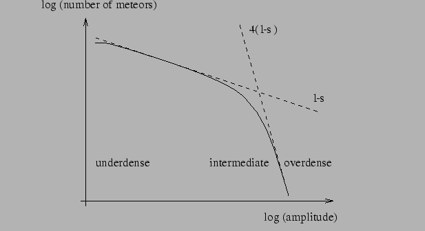 Figure 5 – The structure of a logarithmic cumulative amplitude distribution graph (log A0, log N(A<A0)). It shows two quasi linear parts whose direction coefficients are related to the mass index of the observed meteors.
The amplitude and duration distributions of the meteors depend on the mass distribution of the observed meteors. In logarithmic cumulative amplitude and cumulative duration distribution graphs (see Figure 5), the direction coefficients of the two linear parts in the graph are directly related to the mass index s, a number describing the mass distribution in a stream. Here also, as stream membership determination is not possible with a basic set-up, the mass index of streams is somewhat faulted by the contamination by other streams and sporadics.
Observations of individual meteors
The decay time of underdense meteors yield a measure for the height of the reflection point, which, as we shall see in the next subsection, can be a useful parameter in the reduction of the data. Here also, the result is approximative, as the ambipolar diffusion coefficient – a quantity which rules the trail diffusion, and thus the decay time – does not depend directly on the height in the atmosphere, but rather on the atmospheric parameters: density, composition and temperature. A good atmospheric model can increase the accuracy of the observations somewhat.
Meteor astronomy with a direction-finding system
The set-up considered in this subsection is a “basic set-up”, completed by a system that yields the azimuth and elevation (hereafter called the direction, while another term found in the literature is “angles of arrival”) of the origin of each observed signal, i.e., the direction of the reflection point as seen from the receiver site. A scheme is given in Figure 6.
Many professional radar (backscatter) systems do have such a direction-finding system. These professional systems have resolutions up to 1° . They are based on the comparison of the phase of the received signal at several antennas separated by distances up to a few wavelengths (see, e.g., [14]).
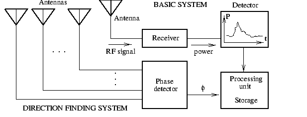 Figure 6 – Scheme of a direction-finding system: next to the basic system, an inteferrometer is set up to determine the position of the reflection points in the sky.
Spatial position of the reflection point
Professional radars also measure the distance to the meteor by measuring the traveling time of a radar pulse. The spatial position of the reflection point can thus be derived, since the direction and distance are known. In forward scatter, distance determinations by radio wave traveling time measurements are not possible, since transmitter and receiver, which are separated by hundreds of kilometers, would have to be synchronized with microseconds precision. However, the direction, together with the estimated height of the reflection point (from the decay time of underdense reflections), can yield an approximate spatial position too. At the zenith, the accuracy of the range determined this way should be about 3 kilometers, while at the horizon it would reach 15 km.
Stream parameters
All meteors from a given stream have parallel paths. Due to the specularity of the reflection, all these meteors will have their reflection points located in one curved surface, that can be calculated.
Now it can be checked whether a particular meteor reflection appears in the reflection surface associated with the stream of interest, and so stream membership can be determined. The parameters measured in the basic system (the flux and mass index) can now be calculated separately for each active stream, without contamination from other streams. To eliminate “false shower meteors,” i.e., meteors that accidentally appear in the reflection surface of a stream but do not belong to the stream, the Fresnel oscillations of each meteor can be measured, to see if they are consistent with the velocity of the stream meteors (of which the direction are known).
Remember that the size of the Fresnel zones is highly dependent on the position of the reflection point (see also [23]). It is thus only when both parameters are known that velocity measurements can be made. With a basic system, both are unknown, so velocity measurements are impossible. With a direction finding system, only the position is known. However, the direction of stream meteors is known, as they are known to originate from a given radiant. We can conclude that with a direction finding system, the velocity of identified streams meteors can be determined, but not that of sporadic meteors.
Ionization in the reflection point
If the gain of the transmitter and receiver antennas are known and vary only slowly with direction in the direction of the reflection point, the received power can be derived fairly accurately, enabling an estimate of the line density at the reflection point through expressions like the equation in Section “Theory of Meteor Reflection”, Subsection “Received power”. This is a first indication of the minimal mass of the observed meteor.
Conclusion
Using a direction finding system it is possible to determine the flux, mass index, radiant and velocity of streams. The flux, mass index and “radiant distribution” of the sporadic background can also be studied. The stream membership of individual meteors can be determined, and in most cases we can estimate the ionization at the reflection point. It is also possible to measure the velocity of individual stream meteors, but not that of individual sporadic meteors.
The real direction of meteoroid flight is unknown with a direction finding set-up. Only a direction perpendicular to the meteoroid flight direction is measured (due to the specularity of the reflection).
Meteor astronomy with multiple receive stations
We now consider a “basic system,” or a “direction finding system,” with, at distances of a few kilometers, several identical “basic systems.” These will be called “secondary stations,” and their observations will be combined with those of the primary station. A scheme is shown in Figure 7.
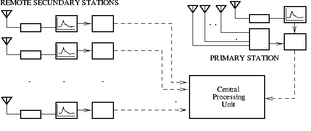 Figure 7 – Structure of a system with multiple receive station: at sites located at a distance of several kilometers from a primary station, secondary stations are set up.
As for each station the reflection geometry on a given meteor trail is slightly different, the different stations will receive signals from slightly different parts of the trail. Consequently, the moment of maximal signal rise (this is the moment at which the meteoroid passes through the reflection point) will be slightly different for the different sites. When the recorders of the different receivers are synchronized, these time differences can be measured. Time differences go up to a few tenths of a second, for station separation distances of typically 5-10 kilometers. Larger distances reduce the chance for a meteor to be observable at all sites, while smaller distances reduce the accuracy of the observations.
Several prestigious professional backscatter meteor orbit systems are based on this principle. To be noted are the Harvard Radio Meteor Project [6] and the Advanced Meteor Orbit Radar Facility [1].
Meteor path determination with a series of basic stations
Consider a set-up with only “basic stations.” In this case, only the time of appearance of the meteor signal and its profile are measured at the different sites. For the path of the meteor to be determinable from these observations, at least six stations have to observe the meteor, since the position (three degrees of freedom) and the velocity vector (another three degrees of freedom) have to be found, and only the time of appearance is an accurate measurement.
The time observations of six stations result in a set of six non-linear equations with six variables. This set is very hard to solve analytically [24]. Furthermore, this method does not take into account the deceleration of the meteoroid body, which can be significant. Though theoretically the deceleration can be introduced by using the velocity information in the Fresnel oscillations, a set-up with only time-determining stations is probably not very feasible, and more than six stations per set-up would be needed in practice, as it is possible that a given meteor is not observable at all station sites.
Meteor path determination when one of the stations is direction finding
If one of the stations is direction-finding, the problem gets much easier, since such a station can determine the direction of the reflection point, and a direction perpendicular to the meteor trail. Now three secondary stations are sufficient to complete the observations, since only the distance, path orientation and velocity are still undetermined. The equation set also gets much easier to solve, especially when fitting methods are used.
Not all three secondary stations are mandatory, however. If one uses the information from the Fresnel oscillations in one station, one secondary station can be left out. By relying on the decay time of the underdense meteors for the determination of the range to the reflection point, a secondary station can be dropped too. Relying on those extra parameters however results in a loss of accuracy of the path determination.
One primary and one secondary station can thus in theory yield an approximate meteor path, and every extra station enhances the accuracy and the chance for the complete observation of individual meteors.
As individual meteoroid trajectories are now measured, unambiguous radiant determination is possible, even with very low meteor rates.
If the Fresnel oscillations from each station are examined, the velocity in the different reflection points can be measured, and thus also the deceleration of the meteoroid.
Meteoroid mass
As already stated, set-ups with secondary stations receive signals from different parts of the meteor trail. If the set-ups are power-calibrated, it is possible to deduce a value for the ionization in the trail for each of the stations. This way, several points of the ionization profile of the meteor trail can be found. By comparing with the ablation theory, this ionization profile can yield the mass of the observed meteoroid. With the previously described techniques, only the mass distribution of a group of meteors could be estimated.
Conclusions
Combining a primary station with a series of secondary stations thus permits the collection of more detailed information on individual meteors. The path, velocity, deceleration and mass of individual meteoroids can now be determined. Information that was previously obtained statistically (like the mass index or radiant) can now be compared with the statistics on individually obtained data.
To be usable, however, the secondary stations have to be synchronized with the primary station. As the time differences between received signals in the different secondary stations can be up to a few tenths of a second, synchronization to one hundredth of a second is probably enough, so standard NTP synchronisation between the different computers involved can be used for synchronization purposes. Of course, a GPS received at each station would be ideal.
There has to be a communication link between the stations to be able to reduce the observations. The most convenient way of communication between the stations is probably the internet. However the data reduction needs not to be done real-time, so data exchange using tape or other media is possible.
General requirements
For receiving meteor scatter signals, a radio transmitter is needed. In amateur meteor forward scattering, existing transmitters are used. Of course, the transmitter has to fulfill some conditions to be usable.
First of all, it must transmit in the right frequency band. Lower frequencies (approximately below 30 MHz) are not usable, because more often than not there is reception of the broadcast through ionospheric propagation, masking the meteoric reflections. Higher frequencies (approximately above 150 MHz) are not suited either, as theory shows the maximal height of observable meteors decreases with increasing frequency, and so do the duration and power of the reflections. Professional systems generally use frequencies between 40 and 70 MHz as a compromise.
Secondly, the transmitter must be distant enough to prevent direct reception of the signal. One can also use a transmitter that is shielded by a mountain. Without mountains, the minimal distance is about 600 km. The absolute maximum is about 2000 km. In theory, it is possible to observe without this requirement, but special methods must be employed.
Last but not least, the power of the transmitter has to be sufficient. Stating a lower limit is not possible, as that depends on the distance between the transmitter and the receiver, the antenna patterns of both stations, the noise figure and bandwidth of the receiver, the method of signal detection, … As a rule, kilowatts of power are needed (though lower power and high gain antennas also work), and the more powerful the transmitter is, the best.
Some classes of transmitters
FM broadcast stations
These transmitters are very popular. Their frequency (87.50 – 108.00 MHz) is quite satisfactory, and the powers range from some watts to a few hundred kilowatts. The main problem is that an enormous amount of transmitters transmit at a given frequency within a radius of 2000 km from a given place, and that finding a clear frequency is difficult in populated areas. One possible solution is the use of RDS (Radio Data System) for the identification of the received transmitter.
Not all countries in the world use the same frequency band for FM broadcasts. In the former Soviet Union and eastern European countries, the band from 65 to 73 MHz is also used. These transmitters are extremely useful for West European observers. Note that only the former Soviet Union countries will keep using this band. From the year 2000 on, all other East European countries will probably have stopped transmissions in the 65-73 MHz band. Japan also uses another frequency band (76-90 MHz), which can be useful for observers in the neighborhood.
TV stations
Several TV channels are located in the lower VHF band. The exact frequency allocations depend on the countries. The bandwidth of these transmitters (about 6 MHz) is wider than that of regular FM transmitters, but one can tune in to the video carrier frequency with a narrow-band receiver. This carrier signal has a constant power, and is not affected by the modulation of the signal.
Aircraft beacons
Aircraft beacons emit between 108 and 136 MHz, and transmit an identification code. However, their power is in the Watts-class (typically 6 W ERP and an elevation angle of 5° for VOR-beacons), which has been experienced to be too little for meteor scatter.
Amateur beacons
Parts of the 50 MHz and 70 MHz amateur bands are occupied by beacons. These are mostly CW transmitters, transmitting a carrier which is regularly interrupted by an ICW or FSK morse code identification, which unfortunately has a low power compared to the broadcast. Lists featuring the location, power, frequency, antenna characteristics and call sign can be found on Internet or in radio amateur publications.
Remarks
Remember that there may be (and most probably are) several transmitters active at the same frequency, and that a particular meteor echo is thus not necessarily powered by your selected transmitter. Identification of the transmitter should be tried, e.g. with RDS for West European FM transmitters.
Some transmitters are not emitting constantly, but stop broadcasting during nighttime.
For a reliable reduction of the observations, the antenna pattern of the transmitter is useful, as it seriously affects the radiated power in the direction of the meteor. This pattern can probably be acquired by writing to the broadcaster.
A good source to look for candidate TV or FM transmitters, is the “World Radio and TV Handbook”. There is an updated version every year.